The panel is divided into four sub-panels. The PC VR panel displays based on selection:
Status
Used to connect the receiver and display the connection status of the receiver.
General Calibration
Used for motion calibration and key parameter configuration during motion calibration.
PC
Used for common parameter configuration and control in general PC motion capture.
VR
Used for common parameter configuration and control under SteamVR motion capture.
Status Panel
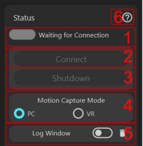
Status Display
Indicates connection status; the icon is green when connected.
Connect Button
The font is gray when not connectable, indicating the receiver is not inserted. The font is white when connectable. If you encounter connection issues, please refer here.
Shutdown Button
Click to shut down all. To shut down a specific sensor, open the sensor details for shutdown (refer here), or place it in the charging box for shutdown (refer here).
Motion Capture Mode Switch, switch according to your usage scenario
Only users using SteamVR need to switch to VR mode. For regular scenarios like recording animations or non-VR live streaming, switch to PC mode. Note that if switched to VR mode and VR is not connected, it will automatically switch to PC mode.
If VR cannot connect, please refer here.
Log Switch
In 3D preview mode, the switch is available. Logs are not displayed by default. The icon on the right clears logs. If 3D preview is closed, logs are displayed by default and cannot be closed.
Help Document Button
Advanced Settings Toggle
Once enabled, all advanced features will be displayed, including: configuration export and import operations, replacing foot sensors with shoulder sensors, double-tapping sensor functionality, outputting SteamVR virtual tracker capabilities on thePCside, communication channel modification, signal transmission strength, magnetic resistance adjustment, etc. Before using these features, please make sure to read the relevant help documentation!!!Export, Save, and Restore Default Settings for All Configurations
Advanced feature, proceed with caution. It is recommended to back up the current settings before using this feature!
General Calibration Panel
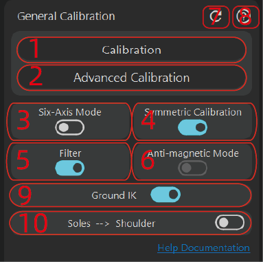
Calibration Button
General calibration requires posing in three postures: A-Pose, S-Pose, T-Pose. For details on motion essentials and calibration, please refer here.
If calibration fails, possible reasons include:
- Wearing does not conform to the wearing mode, please refer here.
- Accidental replacement of points, please refer here.
- USB driver issues, please refer here.
Advanced Calibration Button
Compared to the calibration button, this adds B-Pose, mainly for yaw angle calibration of the head, chest, and waist nodes. Other functions are consistent with
Calibration.Six-Axis Mode Switch
If the user's magnetic environment is poor, six-axis mode can be enabled. Before enabling six-axis mode, it is recommended to calibrate the gyroscope. Six-axis mode means not using magnetometer sensor data, thus not affected by any magnetic environment, but it may cause gyroscope drift, manifesting as yaw angle deviation over long periods of use.
Yaw Angle Deviation (Yaw Angle Slant) Manifestation
- Tilting while standing, such as the chest, results in self-rotation.
- Tilting forward results in bending towards the side front instead of straight ahead.
- While lying down, if the legs are aligned with the body, slanting means the legs form a horizontal angle with the body, such as both legs slanting to the right.
For magnetic environment identification, please refer here.
Anti-Magnetic Mode Switch
- For situations where individual points in the magnetic field environment are poor, anti-magnetic mode can be turned on.
- If you want the sensor to follow faster when the body is slightly swaying, anti-magnetic mode can be turned on.
For example, in the case of swaying left and right, anti-magnetic mode will follow faster compared to non-anti-magnetic mode. Non-anti-magnetic mode follows slower under slight swaying but is not significantly affected under large swaying.
[info] When to turn off anti-magnetic mode
- For users who dance vigorously, it is recommended to turn off anti-magnetic mode and also not to use 6-axis mode. Dance users are advised to perform in a good magnetic environment.
Of course, in the future, we may also release a professional version of the sensor with better gyroscope performance, possibly featuring a vigorous dance mode without using a magnetometer. Stay tuned.
- If the overall magnetic field is very chaotic, such as nearby transformers, or the room has large speakers, and the magnetic field radiation range is wide, or used on an iron spring bed, it is recommended to turn on 6-axis mode.
The anti-magnetic switch is remembered by the tracker, meaning that each time it is turned on and off, the result is stored in the tracker, not in the software configuration.
Filter Switch
Used to smooth motion jitter. It is generally recommended to turn it on. If you find that a certain part is still jittery, check the following:
- First, check if the wearing causes jitter, such as the tracker being suspended
- Check the anti-magnetic level, generally recommended to set to 12. If jitter occurs, adjust to 12 and test again. For adjustment, please refer here
Symmetrical Calibration Switch
This switch is effective only during calibration, mainly to eliminate magnetic yaw angle measurement errors (magnetic yaw angle measurement is based on calibration actions, which have errors, and the magnetic field itself fluctuates, causing measurement errors). It is generally recommended to enable it [6-axis mode will automatically disable it]. Its specific function is to average the yaw angles of the left and right trackers at the same horizontal position during calibration. For example, if the left upper leg's current standing direction measures a yaw angle of 10 degrees and the right upper leg measures 20 degrees, a 15-degree average will be used.
Only when both legs are at the same horizontal height and there is a significant difference in the magnetic field heading direction, it needs to be turned off. Generally, if there is a large magnetic field difference at the same height, it indicates a poor magnetic environment, and it is recommended to use 6-axis.
For magnetic environment identification, please refer here
Reset Button
Resets the parameters of the current panel to default parameters! Subsequent panel functions are the same and will not be repeated!
Help Document Button
Ground IK
Used to adjust the imbalance of both feet, such as when sitting down, one foot is on the ground, and the other foot is 2cm above the ground. It can also alleviate the up and down oscillation problem during the foot switching process.
Replace Feet with Shoulders
Advanced setting, When enabled, feet will automatically be replaced by shoulders, with the left foot corresponding to the left shoulder and the right foot to the right shoulder. After enabling, you need to activate the
AI Engine.Configure which six-axis points enable six-axis functionality
In default six-axis mode, all points have the six-axis function enabled. If you uncheck a point, that point will use non-six-axis mode.
PC Panel
These settings do not affect VR-mode users, so VR users can skip this section.
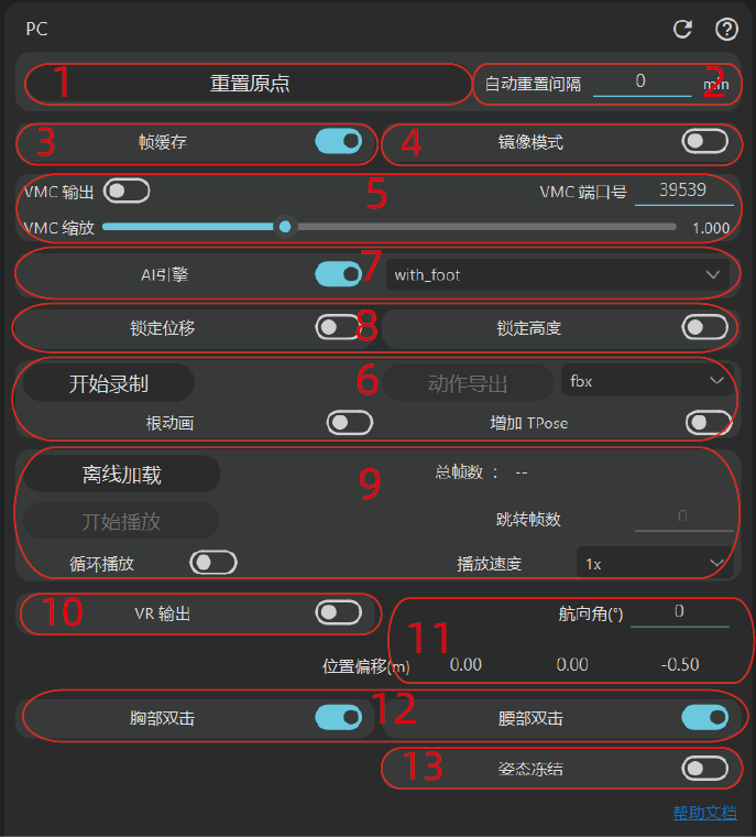
Frame Buffering
By default the PC mode keeps two frames of buffer (~34 ms). Buffering improves stability—for example, it can reduce drift. If you only capture the upper body you can disable it for more real-time tracking. Frame buffering is disabled automatically when
AI Engineis enabled.Mirror Mode
Left-right mirroring, useful for streamers; it works like a mirror, flipping the image horizontally.
AI Engine
After enabling, the character’s overall displacement and foot contact are decided by an
AImodel instead of traditional algorithms and heuristics. The PC version of the AI engine provides two models: one that requires sensors on both feet (with foot) and another that works without foot sensors (no foot). If you select thewith footmodel while no foot sensors are present, it will automatically fall back tono foot, whereas theno footmodel still works when foot sensors are available.Position, Orientation, and Pose
The inertial mocap origin may drift over time. You can reset the origin (i.e., the initial position) directly and also set an automatic reset interval. The default is 0 minutes, meaning no automatic reset. If you set it to
nminutes, the character’s displacement will be reset everynminutesYou can lock the character’s horizontal-plane movement and/or vertical-axis movement. Streamers often need these two features
You can manually adjust the character’s reference position and facing direction. The default is the origin. This is useful for animation or streaming—for example, if a streamer’s room is too small to face the display in a
T-Pose, they can calibrate first and then change the orientation.The position is in the order
x y zusing a right-hand coordinate system, representing global displacement. The positivexaxis points to the right of the screen, positiveypoints upward, and positivezpoints out of the screen toward the user. Maximum value is 99.9 m. The angle represents the character’s facing direction.Pose Freeze is designed for streamers who need to hold a fixed pose to handle miscellaneous tasks or avoid exposing their real posture. When enabled, the pose is frozen at the moment you toggle the switch on; turning it off restores real-time mocap.
External Protocol Output
VMC Output
Users of the VMC protocol will need this. If a third-party application connects through VMC, enable VMC output.
- You can change the port number after disabling output, and then enable it again
- VMC scaling is mainly for fitting skeletons. If the skeleton driven in rebocap does not match the target skeleton, you may see sliding feet, floating feet, or feet below the floor. Adjusting the scale here can mitigate this. However, if you are using a VRM model, we strongly recommend uploading the VRM model and keeping this value at 1.0. If you are using other models and want better results, we also suggest you upload the skeleton—the skeleton can be exported via the Blender add-on; for details please see Blender Plugin Usage
VR Output (Advanced)
When enabled and SteamVR is connected, virtual trackers are automatically output to SteamVR. If you need to change the tracker output nodes, temporarily switch to the
VRpanel, adjust the VR output settings, and then switch back. The positions output here are the tracking points on the current virtual skeleton and are not affected by the HMD. The community has provided instructions for using SteamVR without an HMD. The official team bears no responsibility for any consequences. Chinese only; please use your browser’s translation feature for other languages: https://forum.rebocap.site/t/vmt-rebocap/240Recording and Offline Playback
Recording
Basic workflow: Start Recording → Stop Recording → Export Motion. Three formats can be exported here: fbx, bvh, and dae. Support for
MMDanimation is planned for the future. Among them, fbx6 is the legacy FBX format; many modern programs no longer support it.The exported FBX skeleton is compatible with
Mixamoand can be imported directly intoBlenderand other 3D software. Root motion and adding aT-Poseare optional. By default the mocap moves the hip node; with root motion enabled, the root node moves instead. If you want the animation to start with the defaultT-Pose, enable that option.If you need to create animations with the FBX, be sure to use rotation data rather than the absolute bone directions contained in the exported FBX. We will later invite community members to record tutorials on using mocap data to make animations.
Offline Playback
Purpose: Load and play back exported
.rebo_animraw recording files offline Usage: Click Offline Load, select the raw recording file, and playback starts automatically. It behaves the same as online mode. Before loading you can change the user skeleton, choose whether to useIK, whether to enable theAI Engine, etc., and the changes take effect immediately. Playback speed is adjustable, but this will change the SDK’s output frame rate; there is currently no resampling or interpolation strategy. You can pause, play, loop, etc. After the clip finishes, the play-state button label is not updated—press the play button twice to play again. Recordings are at 60 fps, so you can calculate the target frame number by duration—for example, to jump to 10.5 s, jump to frame 630. Changing the frame number seeks immediately.[info]Using the official default data If users want to know whether their own software can be supported, or simply want to check the effect, they can use the offline data. At the current stage the offline data is a dance video; it is recommended to upload the skeleton in advance, switch to
AI Engine, use thewith footmode, and turn onGround IK. Because the performer wore the tracker on the stomach instead of the hip during recording, it is recommended that in the motion-capture parameters, under theIKsettings, Waist Flexibility be set to 1.3, IK Weight to 1.4, and Leg Bend to around 3.5.Double-tap Calibration – Chest
After this option is enabled, double-tapping the sensor can trigger the function. Double-tapping the chest sensor is used to reset the origin.
Note: Double-tap means tapping the sensor itself, not pressing the button on the sensor twice! Do not accidentally press the button! The interval between taps must be no longer than 0.45 s and no shorter than 0.2 s, and you need to tap with some force.
Double-tap Calibration – Waist
After this option is enabled, double-tapping the sensor can trigger the function. Double-tapping the chest sensor resets the origin, while double-tapping the waist sensor triggers Motion Calibration.
VR Panel
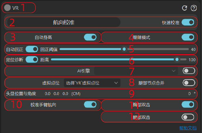
SteamVR connection status indicator
If the connection is successful the indicator turns green; otherwise it is not connected. If the connection fails, please refer to here.
Yaw reset
When performing a yaw reset, make sure the whole body has no sideways angle; only rotate around the body’s side axis. For example, while standing, stay in an A-pose; when squatting, keep the knees pointing straight forward; when lying down, keep the body in a straight line. At present, yaw calibration does not take effect on the arms; support for the arms will be considered later.
This function is mainly used to recalibrate when the yaw drifts. For the manifestation of yaw drift, see here. If you still find drift after calibration, please consider the following three factors:
- The strap itself is tilted.
- The guardian boundary has not been disabled—disable the standalone headset’s guardian boundary.
- A tool such as VRC Toolkit was used to modify the yaw angle; reset it to 0.
The “Quick skip” toggle here is mainly used to shorten the time required for yaw calibration. When it is off, a countdown prompt is displayed; when turned on, no countdown is shown.
Headset position information
Displays the headset position in centimeters. The second value is height, and the right-most value is the headset’s pitch angle.
Prevent foot sliding
When Prevent Foot Sliding is off, body tracking is driven entirely by the headset position, so the feet will not stay fixed to the ground; foot sliding is therefore inevitable in the default mode, although keeping the virtual skeleton consistent with the real body can alleviate it.
In addition, when the avatar’s foot height is greater than about 20 cm, the internal calculation will automatically switch back to the default mode. When Prevent Foot Sliding is on, the soles are forcibly stuck to the floor, producing more natural results in non-fast movements, and is generally recommended for anything other than intense dancing.
Ground collision IK
Used to correct foot imbalance—for example, after sitting down one foot is on the ground while the other is 2 cm above the ground—and to reduce vertical oscillation when the feet switch contact points.
Auto re-center
Auto re-center is triggered when the user remains completely still for about 1 s. The “Re-center threshold” refers to the distance between the current posture and the “follow mode” posture (i.e., driven entirely by the headset). When the distance of any virtual tracker exceeds the threshold, re-centering is triggered. Therefore, if the threshold is set very low, re-centering will occur frequently, and you will observe small instantaneous tracker shifts.
After re-centering, the trackers immediately snap to the positions defined by follow mode. If the result still looks wrong, switch to follow mode to check; the cause may be an incorrect yaw angle or a tilted strap.
Chest | Waist Follow Headset
By default, if the anti-foot-slip option is enabled, the positions of all nodes are determined jointly by the headset and the soles of the feet. After turning on this switch, the positions of the chest and waist nodes are determined only by the headset position.
Virtual trackers
Controls which virtual trackers are shown; you can configure them as needed. For example, arm trackers are enabled by default; you can click here to disable them. If VRC mode is enabled, the upper-leg and lower-leg trackers are merged and placed at the knee position. Players can decide whether to enable this based on their own needs. Enabling VRC mode does not necessarily give better results in VRC; this option mainly moves the virtual trackers to locations that better match VRC IK calculation points, but the final effect depends on many factors, such as whether the virtual skeleton matches the real person.
Auto-hide on shutdown
Automatically hides sensors that are not in use. There is one special case: if the “Merge leg nodes” function is enabled, the foot sensors are exempt from being hidden.
Merge leg nodes
Merges the virtual trackers of the upper and lower legs to the knee joint. This is also the tracker placement recommended by default in VRC, but it does not necessarily produce better results inside VRC!
Positioning diagnostics
This function helps evaluate tracker positioning performance. When enabled, it duplicates a new set of virtual trackers directly in front of you; the unit of distance is centimeters, and the distance can be adjusted with the slider. To see the virtual trackers, it is recommended to switch to the default SteamVR environment! In third-party software such as Reborn or VRC, virtual trackers are generally not visible unless a special mode is used.
Virtual Ground Height
Mainly used to address the issue where, when stepping onto platforms higher than the ground level (for example, after putting the device on) or descending to platforms lower than the ground level, the virtual ground is still calculated according to the original floor height, resulting in poor effects. In other cases, you can also adjust this value based on actual needs. For instance, some players may set the virtual ground height slightly above the real ground (around 3–5 cm), giving the IK solver more space and yielding a better overall effect.
AI Engine
After turning on the AI Engine, 5-point tracking is supported: two trackers on the ankles (recommended about 5 cm above the ankle joint), two trackers on the thighs, and one tracker on the waist. This is the minimum required setup. Other trackers can be worn according to actual needs. If certain trackers are not worn, the AI model will predict the orientation of the foot-sole and chest nodes.
“In-place Locomotion & Replace Position” Feature Toggle
Both of these features are implemented in the rebocap plugin by intercepting the internal controller signals of SteamVR. They have no impact on the official streaming tools such as
steam linkandpico connect, but for VD streaming (VirtualDesktop) they will prevent VD from switching from controller mode to finger-tracking mode. Every time this toggle is enabled or disabled, you need to restart SteamVR for it to take effect.If this feature is turned off, you will not be able to use the In-place Locomotion or Replace Controller Position functions.
In-place Locomotion Configuration Area
This feature requires the above “In-place Locomotion & Replace Position” toggle to be enabled. While in in-place locomotion, the plugin hijacks the controller’s joystick data (you can choose either the left or right joystick) and simulates joystick input through on-the-spot stepping, allowing the in-game character to walk through stepping in place. This can greatly reduce motion sickness caused by joystick locomotion (it provides a certain level of cortical trickery). During stepping-in-place, the default walking direction is straight ahead; the corresponding joystick still controls the walking direction—e.g., you can walk backward. The stepping speed can be adjusted via the movement multiplier, and your own angular stepping speed directly affects forward speed.
By default, once the in-place locomotion feature is enabled, the joystick on the corresponding controller becomes inactive. However, we added a switch that restores joystick functionality when no in-place stepping is detected, which may increase the chance of motion sickness.
Calibrate Arm Yaw Angle
When enabled, if the arm nodes are active, pressing the yaw-calibration button will also correct the yaw angle of the arms. During calibration, we recommend placing your arms symmetrically and naturally against your sides (about a 10–25-degree angle from the chest). Feel free to experiment with arm placement to find the calibration position that feels best.
Replace Controller Position
This feature also requires the “In-place Locomotion & Replace Position” toggle to be enabled. Once enabled, and with both hand output nodes turned on, the rebocap tracker’s points will override the controller output points. The controllers must remain connected during this process. The main purpose is to solve the loss of tracking when the controllers enter the HMD’s visual blind spots.
Note: For some controllers, the ray-casting angle is not aligned with the controller’s direction. In this case, you need to edit
data/replace_controller_angle.txtto compensate. For example,picocontrollers require a value of 25 (rotating the ray forward by 25 degrees). Adjust this based on the controller’s direction in T-pose. After each modification, toggle this feature off and back on for the change to take effect.Double-tap Chest (Advanced Feature)
When enabled, double-tapping the chest sensor triggers the Yaw Calibration function.
Note: Double-tap means tapping the sensor itself, not double-pressing the sensor’s button! Do not press the button by mistake! The maximum interval between taps is 0.45 s and the minimum is 0.2 s, and a certain amount of force is required. During sleep, accidental activation may occur; it is recommended to disable this feature then.
Double-tap Waist (Advanced Feature)
Usage is the same as Double-tap Chest. Double-tapping triggers the Motion Calibration function.
VR Auto Height
This option has been moved to the Skeleton section and is enabled by default. Auto Height infers the user’s height from the HMD height. However, the HMD height measurement is easily affected by the user’s environment and the HMD’s own measurement accuracy. The current formula is: height = headset * 1.05.
In other words, looking up or down during calibration will affect the height measurement. In general, try to keep the measurement error within ±3 cm. If the error is large, consider calibrating the distance between the HMD and the ground.
[danger]Measurement Error Explanation
Large height measurement errors have nothing to do with the rebocap device or the rebocap software itself. Rebocap simply reads the height reported by the HMD and multiplies it by 1.05 to estimate the user’s height. If the error is large, it is usually caused by the HMD’s height measurement error!!!
HMD measurement errors can generally be resolved by calibrating the ground height. If the error is still significant, it is likely due to environmental factors (stand-alone HMDs usually rely on the environment captured by their cameras for measurement). Finding a relatively open area in the room may alleviate the issue.